
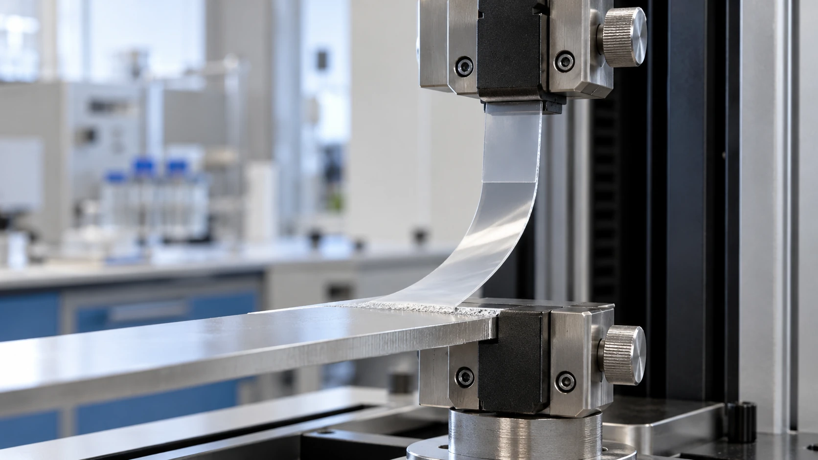
A peel adhesion test measures the force needed to peel a flexible layer, such as tape, film or laminate, from the material it is bonded to at a controlled angle and speed. Peel strength is reported as force per unit width. The peel test method must match the construction, such as a flexible film on a rigid panel or two flexible layers.
A useful comparison starts with that construction and the method, then the reported number. This guide covers angles, standards, the peel strength formula and the evidence needed to compare laminated panels without confusing surface adhesion, packaging seals and panel bonds.
What does a peel adhesion test measure?
A peel adhesion test measures resistance to progressive separation of a bonded flexible layer under defined conditions. The reading describes a material combination, specimen and test method. A tape on metal and a decorative film on wood can therefore require different setups even when both reports use the phrase “peel strength testing.”
| Test object | What separates | What the result helps assess |
|---|---|---|
| Pressure-sensitive tape | Tape from a specified surface | Adhesion under the chosen tape method |
| Label | Label stock from its bonded surface | The tested label-and-surface combination |
| Flexible film on a rigid panel | Film from the bonded construction | Comparative resistance to peeling |
| Flexible bonded sheets | Two flexible layers | Resistance under a suitable flexible-adherend method |
| Packaging seal | Sealed flexible packaging materials | Seal strength under a packaging method |
A tensile tester records force as the specimen separates. Film bending, stretching and the way the layers fail can affect that force. A higher reading is useful only after the construction and conditions have been compared. This is especially relevant when a new film is thicker than the previous one, even if the adhesive stays the same.
A peel result also answers a different question from an abrasion resistance test for laminate. Abrasion tests assess surface wear; peel testing examines separation through a bonded construction. A surface can resist rubbing while its bond still needs evaluation.
Which peel angle should you use: 90°, 180° or T-peel?
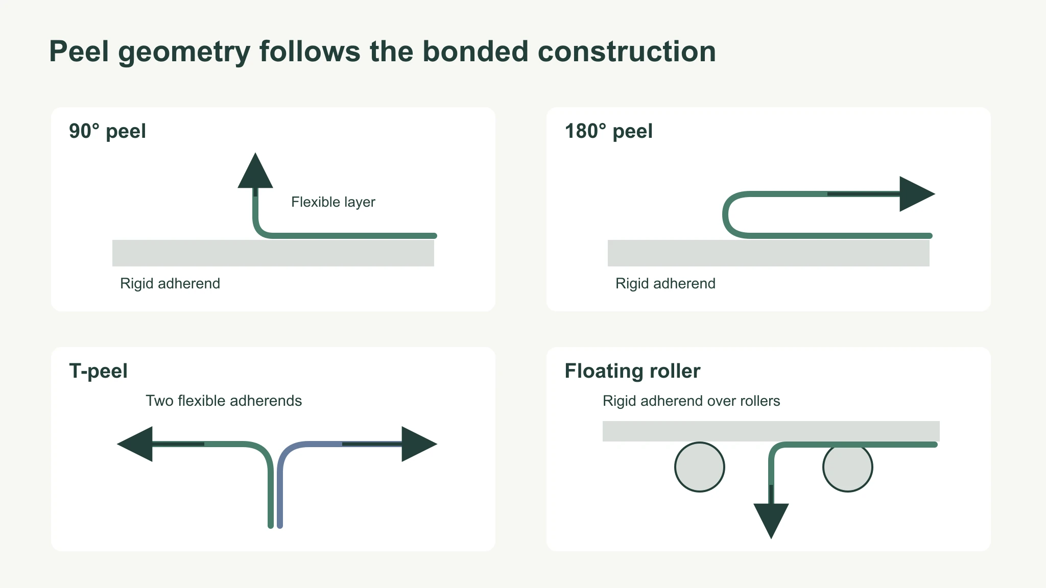
Use a flexible-to-rigid method for a film bonded to a rigid panel and a T-peel method when both bonded layers are flexible. The flexible-to-rigid options include a 90 degree peel, a 180° peel and a floating roller peel setup. Select the geometry that fits the specimen and the governing test method before preparing samples.
In a right-angle setup, the flexible layer is drawn approximately perpendicular to the bonded surface. In a fold-back setup, it bends back along the panel. T-peel pulls the two flexible arms apart; ASTM D1876 describes that flexible-adherend arrangement. A floating-roller fixture supports a different controlled peel geometry for a flexible layer on a rigid adherend.
The angle changes how the peeled layer bends and how force reaches the separation front. Keep the chosen geometry consistent between a baseline and a candidate construction. A unit conversion preserves the reported force per width, but it cannot turn the result from one geometry into the result of another.
For a decorative film that stretches or breaks before a stable peel develops, record that behavior alongside the method choice. It affects what the test can reveal about the interface. Start the comparison with physically comparable specimens rather than grouping all results bearing the same unit.
Which ASTM and ISO standards cover peel testing?
The applicable standard depends on the bonded materials and loading arrangement. Pressure-sensitive tape, flexible-to-rigid bonds, flexible-to-flexible bonds and packaging seals have different methods. The public scopes below identify the starting point; specimen preparation, conditioning and machine settings require the selected standard’s full procedure.
| Standard | Geometry or construction | Use and status to recognize |
|---|---|---|
| ASTM D3330 | Pressure-sensitive tape methods | Tape adhesion; identify the applicable method |
| ASTM D903-98(2025) | Peel or stripping comparison | Comparative adhesive bond testing with controlled preparation and conditions |
| ASTM D6862-11(2021) | Approximately 90°; one flexible and one rigid adherend | Flexible-to-rigid peel resistance |
| ASTM D1876-08(2023) | T-peel; two flexible adherends | Relative peel resistance of flexible bonded materials |
| ISO 8510-2:2006 | 180°; flexible-to-rigid assembly | Current edition, reviewed and confirmed in 2025 |
| ISO 8510-1:1990 | 90°; flexible-to-rigid assembly | Withdrawn; not a current method to specify by default |
| ASTM F88 | Flexible packaging seals | Seal strength; a different application from a furniture panel bond |
The ISO 8510-2 listing confirms the flexible-to-rigid scope and current status. The ISO 8510-1 listing records withdrawal. Check those distinctions when an old purchase specification names a standard without an edition or status.
For a film on a rigid board, the D6862 scope is relevant to the right-angle arrangement. The D903 scope describes a comparative method and the need for defined specimen preparation and conditions. Agree the applicable method with the laboratory before treating historical results as a baseline.
How is peel strength calculated and reported?
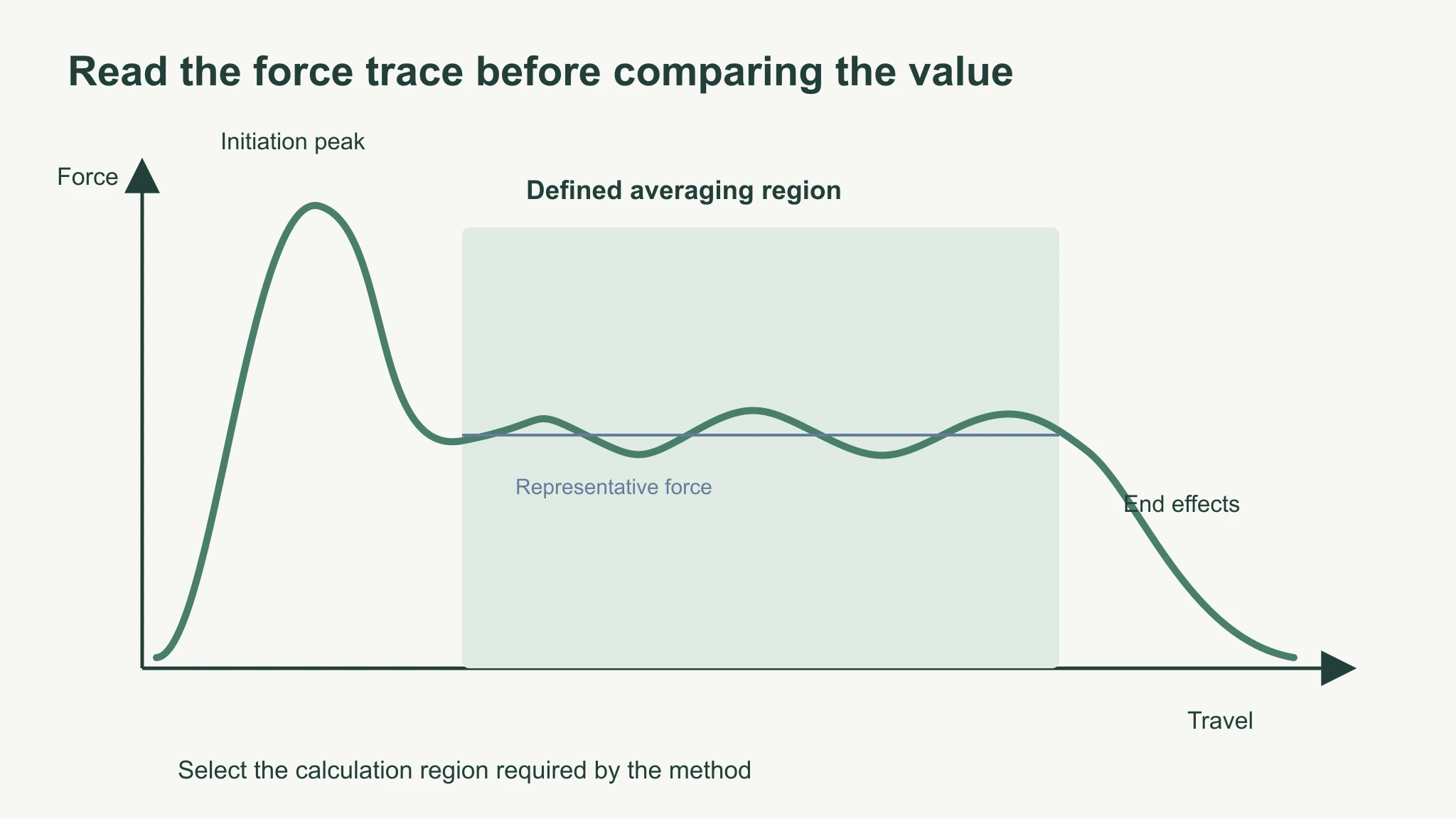
Peel strength is the representative peel force divided by specimen width, using the averaging region defined for the test. Common reporting formats include N/m, N/25 mm and lb/in. A report should identify whether the value is a mean, peak or another statistic so the reader knows which part of the trace it summarizes.
For a hypothetical calculation, an average force of 12 N on a 25 mm wide strip gives 0.48 N/mm, or 480 N/m. This example explains normalization only. The measured width belongs in the report even when results are expressed per standard width.
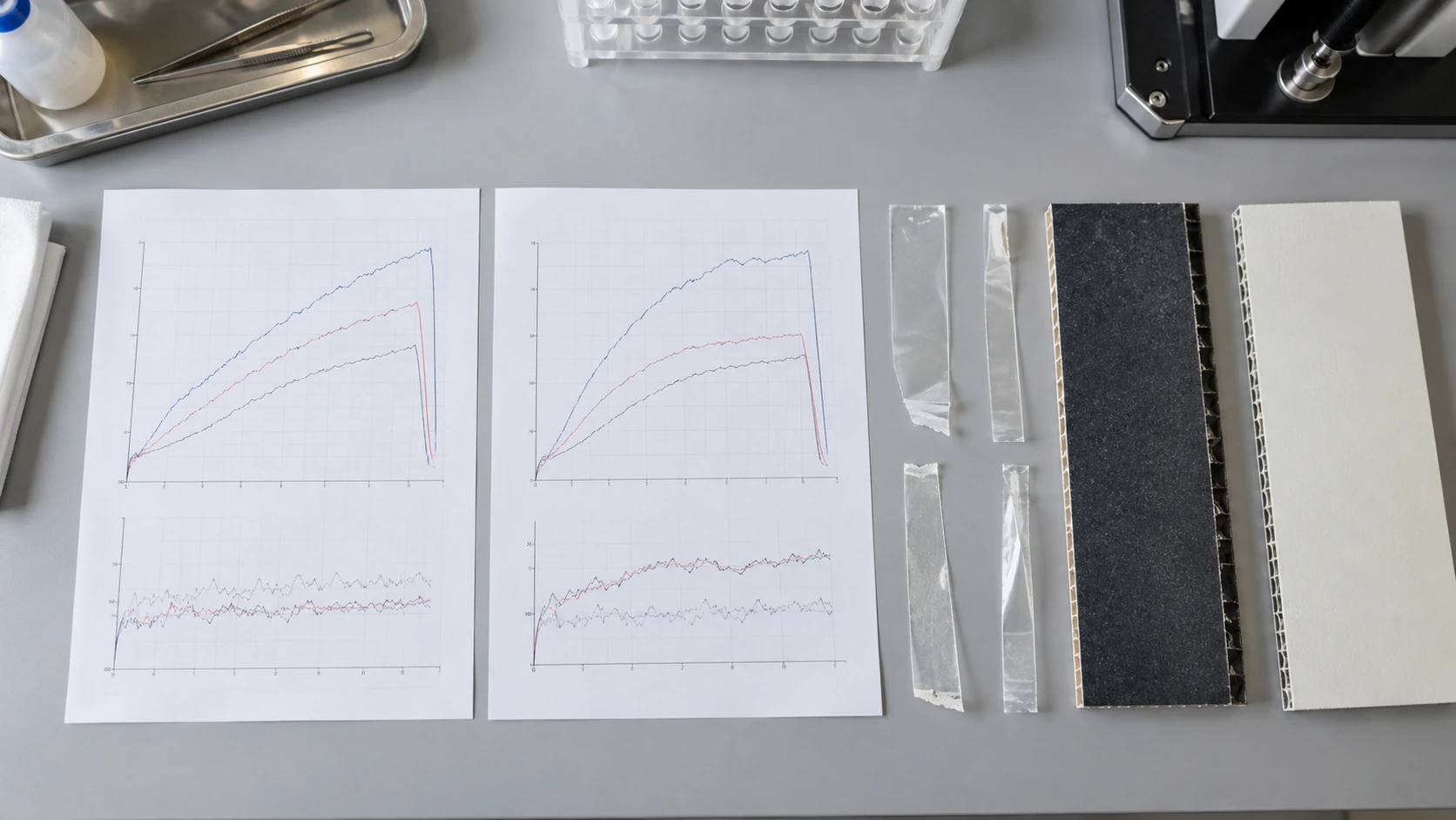
The force trace often contains an initiation peak, a more sustained peel region and end effects. A defined calculation region prevents a short starting peak from being mistaken for sustained resistance. Retain the trace and describe the selected region; include the spread of results and the individual specimens when comparing a change in material.
A report that gives only “maximum force” leaves a different picture from one that gives an average over sustained peeling. For an incoming batch comparison, place the two traces beside each other and establish that both summaries cover equivalent parts of the test. Then compare their reported values, units and failure observations together.
What equipment do you need for a peel test?
A controlled-speed tensile tester or force gauge on a test stand, a suitable fixture and specimen-preparation tools form the basic equipment set. The fixture establishes the peel geometry; the force system needs an appropriate measuring range and resolution. Conditioning facilities and records complete the setup where the selected method requires them.
A peel test machine must hold the rigid part securely and pull the flexible layer without unintended slipping. For a panel specimen, the support and available travel need to suit the test arrangement. For two flexible sheets, the grips must hold each arm in the prescribed configuration. Those differences make fixture selection part of method selection.
Before comparing results from different laboratories, identify the test machine, fixture, force measurement and analysis settings in each report. A shared standard number can still leave different options or reporting choices unresolved. The equipment record should make those choices visible, especially if a prior report contains only a final number.
The practical buying decision is therefore the combination of material, geometry and force measurement needed for the agreed method. A general tensile tester may be suitable with the right fixture, but the presence of a force display alone says little about whether the setup reproduces that method.
How do you test the peel strength of laminated panels?
For laminated panels, use a flexible-to-rigid peel method such as ISO 8510-2 or ASTM D6862 when the face layer can be peeled. Prepare and condition specimens under the selected procedure, separate the face at controlled speed and report force per width. Record adherend thickness and exactly where the construction failed.
| Item | What to specify | Why it affects comparison |
|---|---|---|
| Method and angle | Standard, edition and selected geometry | Establishes the loading arrangement |
| Width and units | Measured strip width and normalized result | Allows force-per-width interpretation |
| Adherends and thickness | Film, board and thickness of each relevant layer | Bending and construction affect the reading |
| Preparation and conditioning | Bonding history and specified conditioning | Identifies the state of the tested bond |
| Speed and calculation region | Test setting and trace region used | Makes the force summary reproducible |
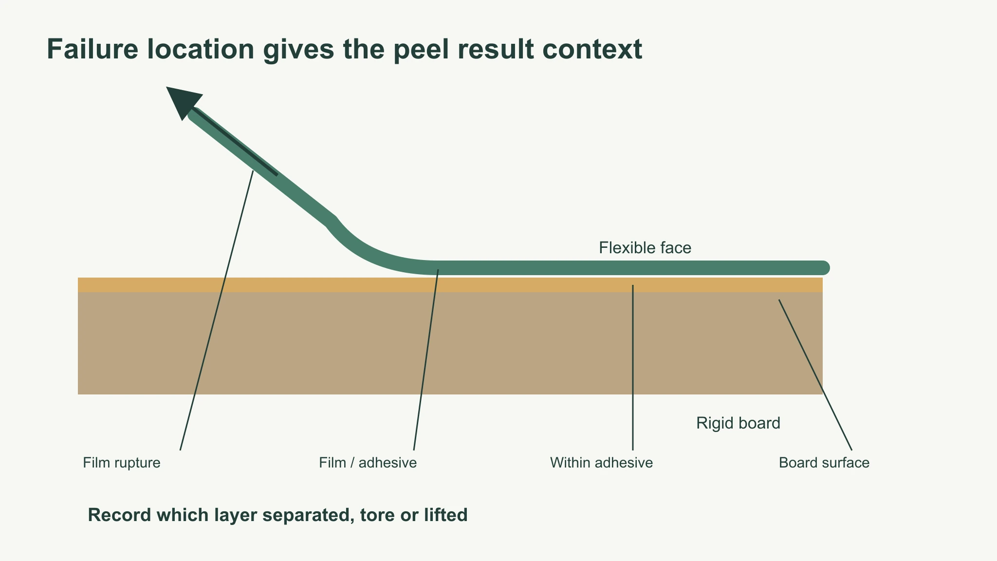
| Failure location | Interface, adhesive, film or board surface | Explains which part limited the measured result |
The thickness point is explicit in the public scope of the right-angle method: adherend thickness influences the result and should be reported. For a film laminated to MDF or particleboard, describe the actual board and face used in the specimen. A description such as “laminate panel” omits information needed to judge the comparison.
As a practical reporting recommendation, distinguish separation at the film–adhesive interface, the adhesive–board interface and within the adhesive. Also record film rupture or board fibers lifting away. When the film tears or the board surface fails, the observed weak layer helps explain the force trace and limits the conclusion about interfacial adhesion.
Compare specimens prepared under the agreed method, preserve their traces and photograph the separated surfaces. If a sample fails differently after a material change, review that location before calling the higher reading an improved bond. Our guide to decorative film delamination causes covers the construction questions that follow such an observation.
What does a successful peel test indicate?
A successful peel test shows that the tested construction meets acceptance criteria agreed before testing, under the stated method, geometry and calculation rules. It does not establish a universal good peel strength or prove service life. The required value and acceptable failure location must come from the application specification.
ASTM D3330 describes using tape-test data with separately defined acceptance criteria. That standard concerns pressure-sensitive tape; a film-to-board construction needs a suitable flexible-to-rigid method. For a laminated-panel comparison, agree the following with the laboratory and customer:
- Required result: state the force-per-width limit, units and reported statistic. A removable layer may need an upper limit or range rather than the highest possible value.
- Acceptable failure: identify which separation locations the specification permits. Film rupture, lifted board fibers and separation at an adhesive interface describe different limits of the construction.
- Condition of the bond: specify any required conditioning or aging before evaluating the result. Compare a candidate with a baseline prepared and tested under equivalent conditions.
ASTM D903 provides a comparative test method, rather than a universal panel-bond acceptance value. Put the agreed criteria in the product specification or customer agreement before interpreting a report as a pass.
How do peel, pull-off and tape adhesion tests differ?
Peel testing progressively separates a flexible bonded layer, pull-off testing loads a bonded fixture perpendicular to a surface, and coating tape tests rate how much coating a tape removes. The stress arrangement and reported result differ, so choose the test that answers the material question before comparing its output.
The ASTM D4541 public scope concerns portable pull-off testing of coatings on metal substrates, with limitations and considerations for other substrates. The test can reveal the weakest plane within the loaded coating system. For a painted component, that is a different construction and loading situation from peeling a film strip along a board.
ASTM D3359 rates coating adhesion by tape on a scale from 0 to 5, and its public description says the method suits lower adhesion levels and gives no absolute force for bond rupture. Those ratings cannot be converted into a peel-force-per-width value for a laminated panel.
For paint and pipe coating questions, start with the applicable coating test specification. For decorative film on a rigid furniture panel, start with whether the face can form a peel specimen and what interface needs evaluation. That distinction helps a laboratory select a useful test without replacing the original question with whichever fixture is already installed.
Where does decorative film fit in peel testing?
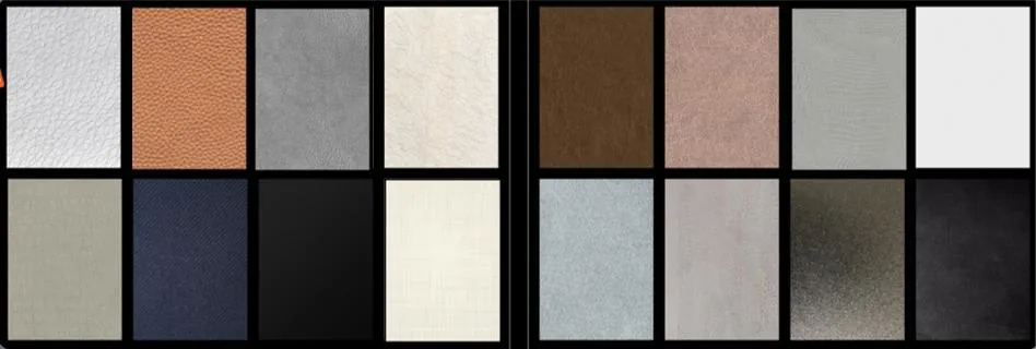
Puremorfilm supplies silicone functional surface decorative film, mainly in rolls for PUR flat lamination; laminated panels are available on request. Its silicone functional face is a new paint-free option distinct from PVC, melamine, PP and PETG decorative faces. Flame-retardant properties are standard for the film; a required fire rating needs evidence for the proposed grade and complete panel construction.
In the manufacturer’s laboratory tests, coffee, red wine and soy sauce left at 25°C for 24 hours were wiped away with no obvious change. The film uses a No DOP formulation. Evaluate a furniture decorative film bond on the actual laminated construction described in the panel report.
The substrate, adhesive and process belong in that bond assessment. Our PUR adhesive for PET film lamination guide explains the adhesive topic separately from the measured peel result. The film is unsuitable for floors, worktops, stove tops, shower floors and other walked-on areas.
How do you get peel results you can compare?
Compare results only after the method, construction, conditions and failure location match closely enough to answer the same question. For a laboratory evaluating a replacement film, agreement on those items comes before ranking final numbers. For a buyer reading reports, the same checks show where further evidence is needed.
- Match the method and geometry to the bonded materials.
- Compare widths, units and the statistic calculated from the force trace.
- Match the adherends, thicknesses, preparation and conditioning.
- Check speed and the region used for the reported average.
- Read the failure observations beside the result.
A tape-to-surface result belongs with comparable tape results. A panel specimen with lifted board fibers needs interpretation in terms of that board failure. For manufacturers evaluating our film, we can provide product information to identify the material being assessed. Contact us with the substrate, adhesive type and proposed test method.
Frequently Asked Questions
How do you determine adhesive strength?
Adhesive strength is assessed with a method matched to the joint’s loading, such as peel, shear or pull-off testing. The result describes the bonded materials under the selected conditions. A peel result is most useful when its geometry, construction and failure mode match the joint being evaluated.
What tape should you use for an adhesion test?
The applicable coating test method determines the tape, and ASTM D3359 notes that no single tape is likely to suit every coating. A film peel specimen instead tests the bonded layer itself. Identify which test is being requested before buying tape, because a coating removal rating and a film peel-force result answer different questions.
What is the ASTM standard for peel testing?
The relevant ASTM standard depends on the construction: D3330 addresses pressure-sensitive tape, D6862 a flexible-to-rigid right-angle setup, and D1876 a T-peel arrangement. D903 provides a comparative peel or stripping method. The standard number and chosen method belong together in the test specification.
What is a pull-off adhesion test?
A pull-off adhesion test loads an attached fixture away from a coated surface and records the system’s response or failure. The report should identify the plane that separated. Its perpendicular loading differs from the progressive separation of a flexible layer in peel testing.
What unit is peel strength reported in?
Peel strength is reported as force per width, commonly N/m, N/25 mm or lb/in. Keep the specimen width, geometry and reported statistic with the value. Matching the unit allows arithmetic comparison; matching the method and construction makes that comparison useful.