
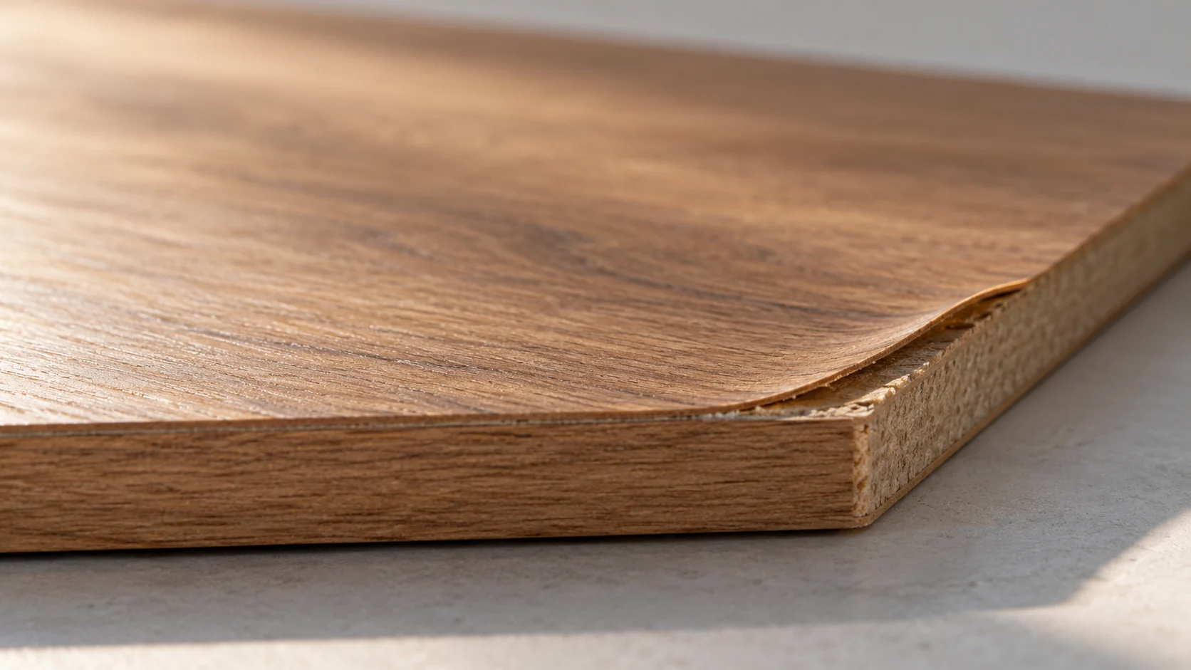
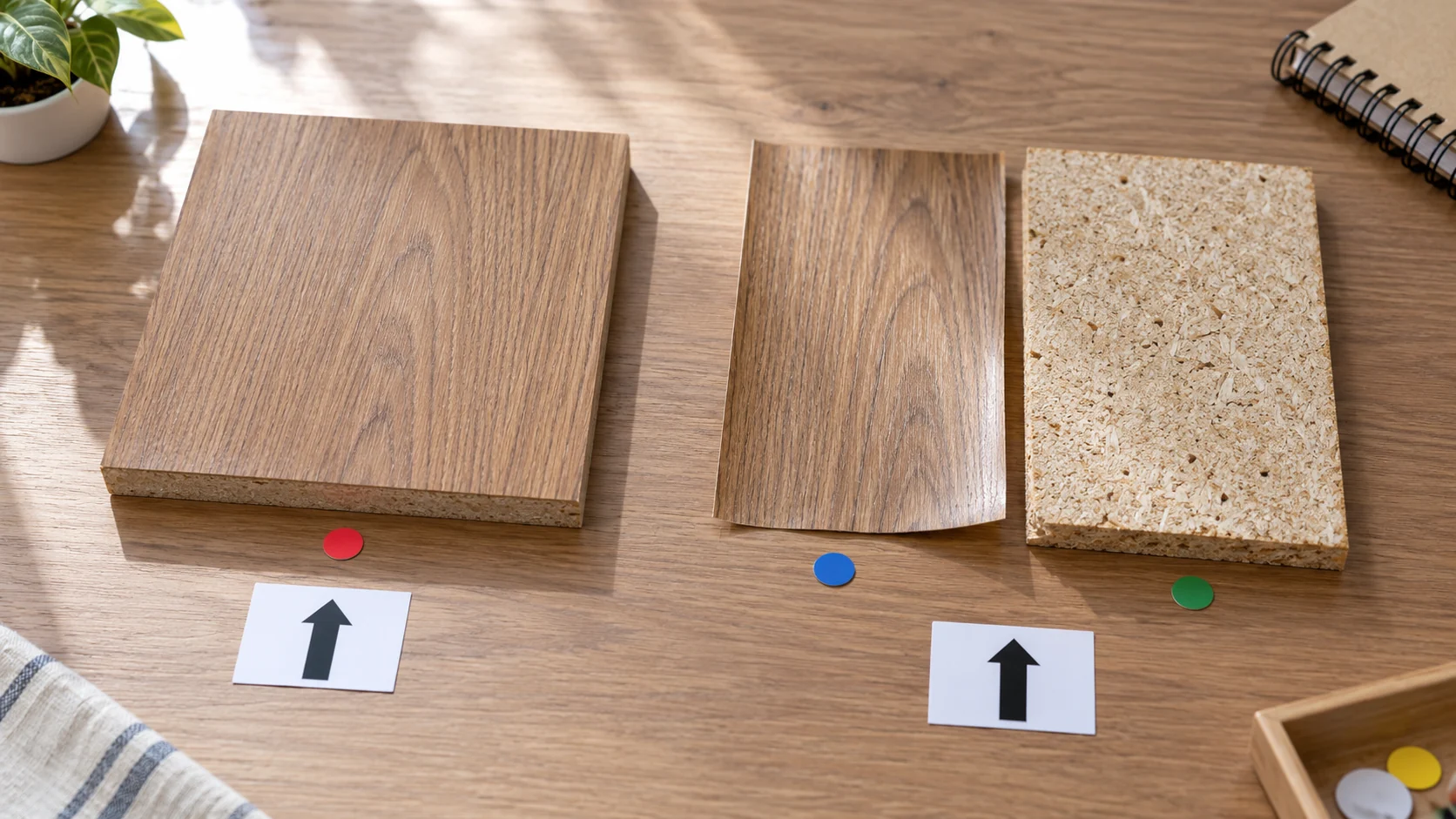
Decorative film delamination causes include weak interfaces, uneven adhesive coverage, incomplete cure and a damaged board surface. Bubbles, orange peel, wrinkles and lifted edges also call for checks on contact, coating smoothness and film handling. Locate the defect and compare a sound panel before changing the process.
Which checks fit the five common lamination defects?
Separate the visible symptom from its possible cause, then compare the faulty film, adhesive layer, board and process with a sound control. The table covers decorative film flat-laminated to rigid boards; it is a set of diagnostic hypotheses, not a universal machine recipe.
| Phenomenon | Possible causes: film / adhesive / board / process | Checks that separate the causes | Corrective trial and release boundary |
|---|---|---|---|
| Bubbles: raised pockets, immediately or after storage | Film: poor wetting of the bonding back. Adhesive: gaps or entrained air in the applied layer. Board: dust, loose surface or uneven face. Process: air trapped as the film enters the nip. | Mark the first stage of appearance. Inspect a cross-section and both exposed faces; compare coverage and nip contact across the width with a sound panel. Compare affected and sound board condition. | Remove the demonstrated contamination or coverage fault; correct entry/contact using the machine maker’s procedure. Trial one adjustment at a time. Hold blistered stock until bond and appearance checks pass. |
| Orange peel: a rippled reflection without an open blister | Film: existing texture or distorted film. Adhesive: uneven coat, particles or poor levelling. Board: roughness telegraphing through the face. Process: coating/application conditions mismatched to the selected grade. | View unbonded film, clean board and bonded face under the same raking light. Inspect the adhesive coat and roller condition. A smooth loose film with a rough bonded face points downstream, but does not identify one cause by itself. | Clean or repair the identified coating surface; restore the qualified deposit and grade-specific application window. Recheck appearance after cure. Increasing heat or glue without identifying the texture can worsen the face. |
| Wrinkles: a fold or crease, often following the feed direction | Film: distorted or damaged incoming web. Adhesive: tack or coverage holding a crease already present. Board: bowed or uneven support. Process: uneven tension, unwind alignment or nonparallel rollers. | Inspect the web before adhesive contact and at nip entry. Mark the cross-web position; check unwind tracking, roller alignment and tension according to the machine instructions. Compare incoming film and board flatness. | Correct the demonstrated feed or alignment fault and re-run retained material. Quarantine permanently creased film; do not try to flatten a bonded crease into an accepted cosmetic surface without a qualified rework route. |
| Delamination: facing separates at an interface or inside a layer | Film: weak internal layer or unsuitable bonding back. Adhesive: incompatible grade, poor coverage or incomplete cure. Board: weak fibers or damaged surface. Process: assembly outside the usable window or stress from later operations. | Photograph both fracture faces and locate film/adhesive/board failure before scraping. Compare matched coupons at the same cure age and exposure; keep the actual failure plane with each measured force. | Correct the verified interface or cure fault on a trial. An internal film split needs film-supplier assessment; a broken or swollen core needs core/part assessment. Re-gluing the visible edge alone does not qualify the panel. |
| Edge lifting: a margin or corner releases while the centre holds | Film: recovery forces or local damage. Adhesive: a starved margin or unsuitable initial grip. Board: damaged, dusty or moisture-affected edge. Process: missed edge consolidation, late assembly or premature trimming. | Compare centre and margin coverage, usable assembly time and contact. Note whether lifting started before cutting, after trimming or after moisture exposure. Inspect for board fibers and swelling. | Restore continuous edge contact within the grade’s window; correct a damaged edge or subsequent operation as demonstrated by the trial. Replace parts whose core or internal film cannot be restored to the agreed specification. |
The USDA wood-bonding chapter explains wetting, surface quality and consolidation. KLEIBERIT’s flat-lamination guide identifies smooth bonding as important beneath thin decorative faces. A machine builder’s defect guide adds useful checks for entry geometry, tension and alignment; its roll-to-roll winding advice is a different process from rigid-board release.
Record the defect before the nip, at press exit, after cure and after trimming where those stages are relevant. A raised pocket and a rough reflection can look similar in a complaint photo but require different checks. The PUR flat-lamination parameter guide keeps named adhesive examples with their own conditions.
Which layers are actually separating?
Delamination is separation between the layers of a laminate. When a decorative face lifts off a board, the break can be at the adhesive interface or inside the board itself, so sketch the real construction before you blame the film or the glue.
The film can have several layers of its own, such as a functional surface, print and carrier. Lamination adds one more joint, between the finished film and the rigid board. So the failure can sit inside the film, at the adhesive joint or in the core.
| Location of separation | What the damaged sample may show | Where the investigation starts |
|---|---|---|
| Inside a multilayer film | A thin film or printed layer separates while the outer film-to-board joint remains attached | Film construction, interlayer bonding, coating and bonding history |
| At the film-to-board joint | The facing lifts away from an otherwise intact board | The two bonding surfaces, adhesive application and cure |
| Within a wood-based board | Board fibers remain attached to the lifted facing and material is missing from the core | Core integrity, surface preparation and moisture history |
Photograph the sound area next to the defect and label the exposed layers. Keep the separated pieces together. “The wood-grain face peeled” describes what you see, not which joint failed. For the board itself, laminated MDF faces and cores explains what sits under the visible finish.
For the full sequence from board preparation to bonding and inspection, see how to laminate MDF.
What does the fracture surface tell you?
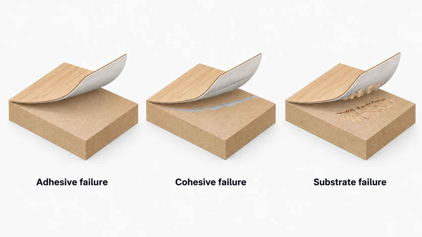
Whatever is left on each separated face tells you whether adhesion failed, the adhesive split, or the substrate broke. Look at both faces before you clean, scrape or add glue.
Adhesive failure happens at an interface. Cohesive failure happens inside the adhesive, leaving adhesive on both sides. Substrate failure breaks the film, coating or board itself. A NASA bonded-joint study identifies these fracture locations in composite specimens. Failures are often mixed, so inspect the whole damaged area rather than judging from its cleanest corner. ISO 10365:2022 gives a common vocabulary for describing bonded-assembly failure patterns.
Wood fibers stuck to the lifted facing send you in a different direction from a clean release off the board. The USDA Wood Handbook describes a wood bond as a chain of wood, adhesive and the zones where they meet, and a weak surface layer can break before the rest of that chain.
| Observation | Useful next check | Explanation still unresolved |
|---|---|---|
| Adhesive stays mainly on one side | Identify the released surface and compare it with a sound sample | Adhesive compatibility or the condition of the released surface |
| Adhesive residue appears on both sides | Examine cure history and the adhesive’s condition | Cure and interface quality elsewhere in the joint |
| Printing or coating transfers with the adhesive | Identify whether the coating split or released from its underlying film | Whether the coating failed internally or released from the base film |
| Fibers or core fragments remain on the facing | Compare the damaged substrate with an intact area | The condition of the deeper core and other joints |
Treat these as screening observations. With very thin coatings, you may need magnification or a lab to see the failure plane.
Why can a clean film still bond poorly?
Because a spotless surface can still resist wetting, so the liquid adhesive fails to spread across it. Cleaning and surface treatment fix different problems, and both have to happen on the side you bond.
Surface-treatment equipment maker Enercon explains that corona treatment raises film wettability, that the effect can fade in storage, and that handling contamination and migrating additives can also change the surface. Its bump-treatment explanation adds that a dyne reading measures wettability and does not guarantee adhesion.
Compare the failed material with a retained good sample of the same construction. Note which side was bonded, how the roll was stored, and whether failures follow a film lot or a storage period. Measure the film at the bonding step and record where you sampled.
If print, primer or another coating sits in the joint, show it on the construction drawing. The adhesive bonds to that coating, so its surface is the one that counts. A side-by-side test against an otherwise identical unprinted specimen helps isolate the coating’s effect.
Don’t treat the decorative face to fix a suspected problem on the back. Confirm the failing interface first, then trial a preparation change on a test piece.
How do application and cure errors weaken a laminate?
Patchy coverage leaves weak areas, and wrong mixing or incomplete cure stops the adhesive reaching the properties it should have. Check the application record and the adhesive’s condition before the next production step.
Even spreading, usable pot life, mixing and assembly timing all affect wood bonding, according to the same handbook chapter. Compare coverage and application records for the wood-side joint, and test retained specimens at the same stage of cure.
Map where the defects are. A repeating stripe points to local coating coverage; failure across a whole run points to mixing, material or cure conditions shared by the run. Those patterns tell you what to check first, not what caused it. Match the application records to the defect locations.
With a reactive adhesive, handling strength comes before full cure. Record the components and mixing for multi-part systems, along with the times of application and each later operation. Waiting longer won’t fix a wrong formulation or a badly mixed batch.
For board lamination, the procedure for laminating an MDF panel covers assembly preparation; aim the next trial at a cause you have confirmed.
Why does failure appear during a later operation?
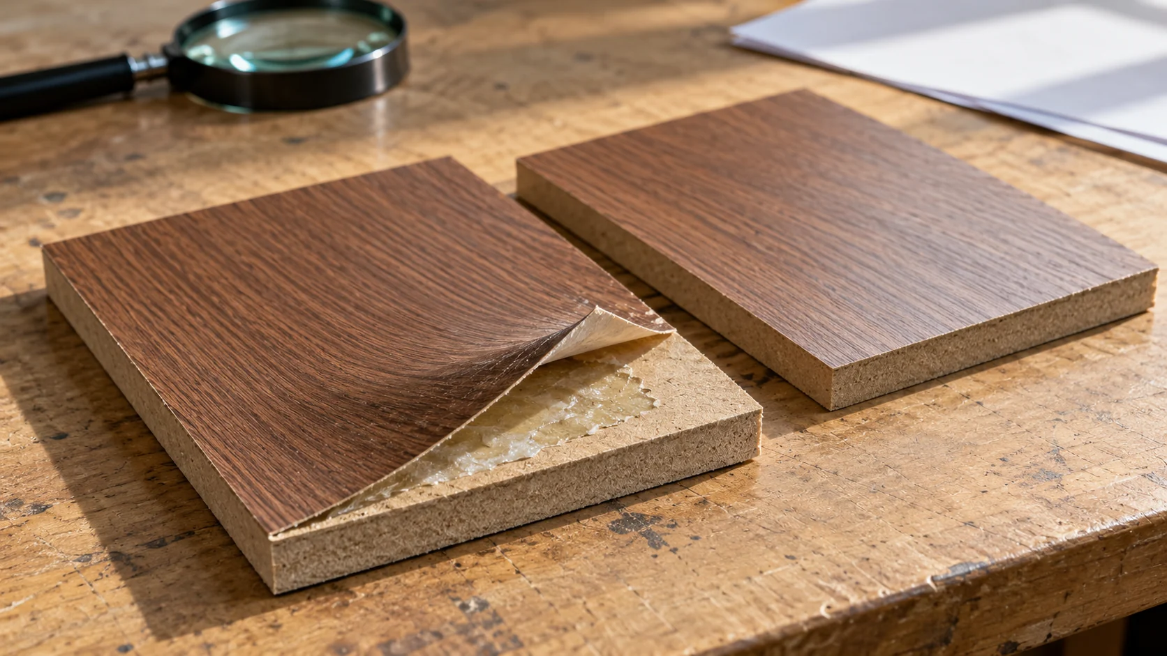
Because cutting, handling or installation adds strain or heat that exposes a bond that was already weak. When the separation shows up gives you a comparison point, not necessarily the moment the weakness began.
Compare retained panels from before and after cutting, handling or installation. Mark where lifting first appeared and whether the exposed interface follows a cut edge, a corner or a wider area.
Check whether the facing was lifting before the cut, whether the core fractured at the cut, and whether the defect runs beyond it. Saw damage and an already weak bond can both be present.
Keep the failure location and production stage together in the record. “Failed after cutting” means far more with before-cut specimens and photos of the exposed joint.
How can moisture and service exposure reveal a problem?
Moisture swings stress wood-based laminates, and real service conditions can expose a bond that passed its first tests. Compare the failed assembly’s exposure with an intact control.
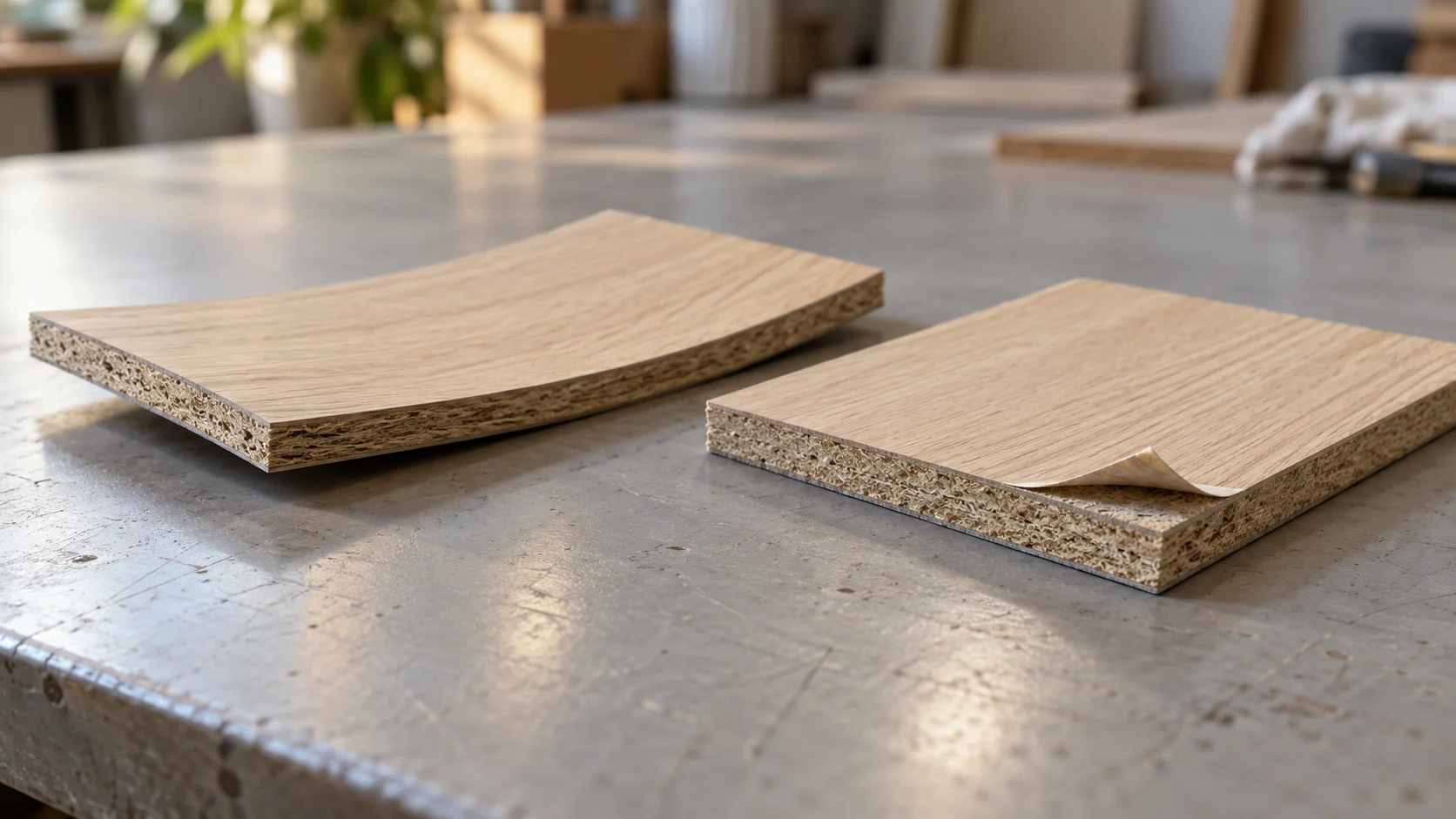
For particleboard and MDF, the Composite Panel Association’s warp guidance explains that different moisture conditions and expansion behavior create stresses between a laminate and its substrate, and that uneven exposure of the two faces causes warp. Record curvature and layer separation separately; a warped panel can still have a well-attached facing.
Look for a link between separation and damp edges, a nearby leak, a newly humid room or one face of the panel being exposed. Compare damaged and sound areas of the same installation, and check the core and cut edges for moisture damage; MDF moisture limits explain where the board is suitable.
For heat or chemical exposure, record the actual event and where it happened before you choose an aging test. A defect only in the exposed area needs a different comparison from one already present in unexposed stock. Test the complete construction, because a different substrate, adhesive or coating is a different assembly.
If several things changed at once, list them separately. Photograph the fracture surface before cleaning and note moisture conditions when the failure is first found.
How should you store decorative film rolls before lamination?
Store decorative film rolls in their protective packaging, away from sunlight, dirt, moisture and local heat sources, within the supplier’s documented conditions. Support each roll using the approved pallet, cradle or core arrangement. Rotate stock by receipt date and let sealed rolls reach the lamination-room conditions before opening them for use.
| Storage check | Practical action | Information needed |
|---|---|---|
| Temperature and humidity | Monitor the storage space and avoid rapid changes or condensation. | The supplied grade’s written storage limits; do not borrow another product’s numbers. |
| Flat storage or core suspension | Use only the support and orientation approved for the roll size and core. | Supplier instructions for cradles, pallets, suspension and stacking; protect roll faces and edges. |
| Stock rotation | Use first-in, first-out within the stated shelf life and keep identification readable. | Receipt date, lot number, package condition and the grade’s shelf-life statement. |
| Before lamination | Allow packaged rolls to acclimate, then inspect for moisture or damage. | Supplier-approved acclimation and line conditions before releasing the roll. |
Poor storage and handling belong among the decorative film delamination causes to rule out before changing the process. Request grade-specific storage and acclimation guidance from the film supplier before setting limits, and include material condition in the panel lamination adhesive checks.
Which checks should come before changing the process?
A matched comparison of failed and sound material, the failure plane identified, and a test suited to the construction. A hand peel shows where a joint separates, but it gives you no repeatable acceptance value.
These five checks organize an investigation before rework:
- Preserve the failed pieces and an intact control, with their orientation and location marked.
- Compare specimens at the same relevant age and document their storage and exposure histories.
- Select a suitable test geometry, then keep specimen preparation and test conditions consistent.
- Record both the measured result and the material left on each separated surface.
- Trial one proposed correction and repeat the comparison before releasing production.
ASTM D903-98(2025) covers comparative peel or stripping characteristics under defined preparation, temperature and machine-speed conditions. ASTM D1876-08(2023) covers T-peel resistance between flexible adherends. Use T-peel for a flexible-to-flexible construction and a suitable facing-peel setup for a rigid board.
Set the acceptance limit for the actual construction and use. Report specimen width, test conditions and failure mode with every force value, so supplier or process comparisons mean something.
What should a delamination investigation record?
The construction, the failed interface, the process history and a matched test result, so the film, adhesive and board suppliers all look at the same problem. A sample and a complaint photo leave too many open variables.
| Item | What to specify | Why |
|---|---|---|
| Construction | Every film, coating, ink, adhesive and substrate in order, with the bonding side marked | Identifies the interfaces that could have failed |
| Material identity | Supplier, grade, lot and relevant storage history | Allows comparison with retained and successful material |
| Adhesive application | Product identity, batch, mixing records where applicable, coverage checks and run location | Locates variation within the chosen adhesive system |
| Cure and operation sequence | Application, handling, machining and testing times with recorded conditions | Allows the failed and control specimens to be compared at equivalent stages |
| Failure evidence | Photographs of both faces, defect map and first observed production stage | Preserves evidence that cleaning or repair would remove |
| Service exposure | Location, moisture events, heat or chemical contact and condition of nearby intact material | Identifies exposure differences worth testing |
| Validation | Method, specimen preparation, results, failure mode and acceptance criterion | Makes the proposed correction reviewable |
Ask for the smallest trial that can tell the leading explanations apart. If you suspect contamination, compare controlled preparation on the same material stack. If the board is damaged, an adhesive trial on a different, sound board answers a different question.
Log what changed between trials. A good sample made after changing film, adhesive, press settings and board all at once doesn’t tell you which change fixed it. You can qualify it as a new construction, but the original cause stays unknown.
For a peel comparison, complete the fields below before running the specimens. ASTM D903 is a comparative peel/stripping route where a suitable specimen can be made; T-peel applies to two flexible adherends. A rigid MDF board cannot simply be treated as a second flexible strip. Agree preparation with the testing laboratory and record exceptions rather than calling every hand pull a standard test.
| Peel-test record | Record on every compared specimen |
|---|---|
| Construction and interface | Film and backing, adhesive grade/lot, core, bonding side, specimen orientation; mark film-internal or film-to-board joint. |
| Geometry | Method/version, peel arrangement and angle, specimen width, flexible or rigid adherends; keep geometry identical across candidates. |
| Test conditions | Test speed, conditioning/cure age, temperature, humidity and any exposure; obtain values from the agreed applicable method, not this table. |
| Result and acceptance | Measured force, unit and averaging rule; agreed acceptance value; photograph adhesive/cohesive/substrate failure on both faces. |
Keep film-internal peel results separate from the PUR-to-board result. A supplier’s force per strip width becomes comparable only when geometry, conditioning, speed, units and failure plane match. The acceptance value belongs to the agreed finished construction; no general pass force is supplied here.
Where does silicone-surface decorative film fit?
Puremorfilm manufactures silicone decorative film in China with a silicone functional face on a PET support. We supply rolls without self-adhesive backing for PUR flat lamination to boards, or silicone laminated panels quoted per project. Use the current product for furniture fronts, cabinet doors, wall panels and other vertical or low-wear faces; exclude floors, countertops and stovetops.
A fault in the silicone-to-PET construction calls for review of the supplied film. A fault at the PET-back-to-board joint calls for review of the PUR grade, preparation, contact and cure. Keep those interfaces separate when you send a failed sample.
Standard furniture and wall-film rolls start at 500 m. Laminated panels are 1220 × 2440 mm and start at 200 sheets; the core and facing configuration are quoted per project. Compare the furniture decorative film and wall-film application with your component.
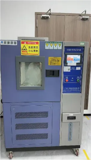
Illustrative equipment image; not a record of testing this finished panel.
What should you do after identifying the failed interface?
Hold the affected stock and choose a controlled rework trial, remanufacture or component replacement according to the failed layer and remaining material condition. A pressed-down edge is not evidence that the construction has recovered.
| Disposition | When to evaluate it | Before release |
|---|---|---|
| Controlled rework trial | Local film-to-board release with a sound core, where the material/adhesive suppliers can define a viable preparation and rebonding route. | Treat the repaired bond as a changed process. Check appearance, bond, edges and the relevant exposure against a sound control. |
| Remanufacture the facing or component | Widespread bond failure, permanent wrinkles, objectionable glue-line texture, or an internal film split that a local treatment cannot remove. | Use sound materials and the corrected process; inspect the whole remade part rather than the repaired spot only. |
| Replace a damaged component | Swollen, fractured or weakened core, or a component that cannot meet the original dimensions and service requirements after rework. | Resolve the moisture or machining cause before replacement parts are installed. |
Keep failed pieces before any repair removes evidence. Trial the proposed correction on matched material, test at the agreed cure stage, and document the failure location as well as the result. A visually improved face can still have a weak bond.
For a flat furniture or wall-panel project, contact Puremorfilm with the construction, defect-stage photos and the film/adhesive/board trial record.
Frequently Asked Questions
What would cause delamination?
A poorly prepared bonding surface, uneven adhesive coverage, wrong mixing or incomplete cure, mechanical strain and unsuitable service exposure. Identify the separated interface first.
What is the difference between debonding and delamination?
Debonding is loss of adhesion at a joint; delamination is separation between the layers of a laminate. They overlap when the adhesive interface between two layers fails.
Is delamination fixable?
Yes, some localized film-to-board failures can be evaluated for controlled rework when the core is sound and a suitable rebonding procedure is available. Widespread failure, an internal film split or a damaged core may require remanufacture or replacement. Validate the revised part before release.
Can wrong adhesive cause delamination?
Yes, an adhesive unsuited to the bonding surfaces or the exposure can cause it. Confirm the failure plane first, because poor coverage, a damaged coating or a broken core look similar.
Does curing time affect bond strength?
Yes, a reactive adhesive gains strength as it cures. Compare specimens at the same age; extra waiting won’t fix a wrong mixture.