
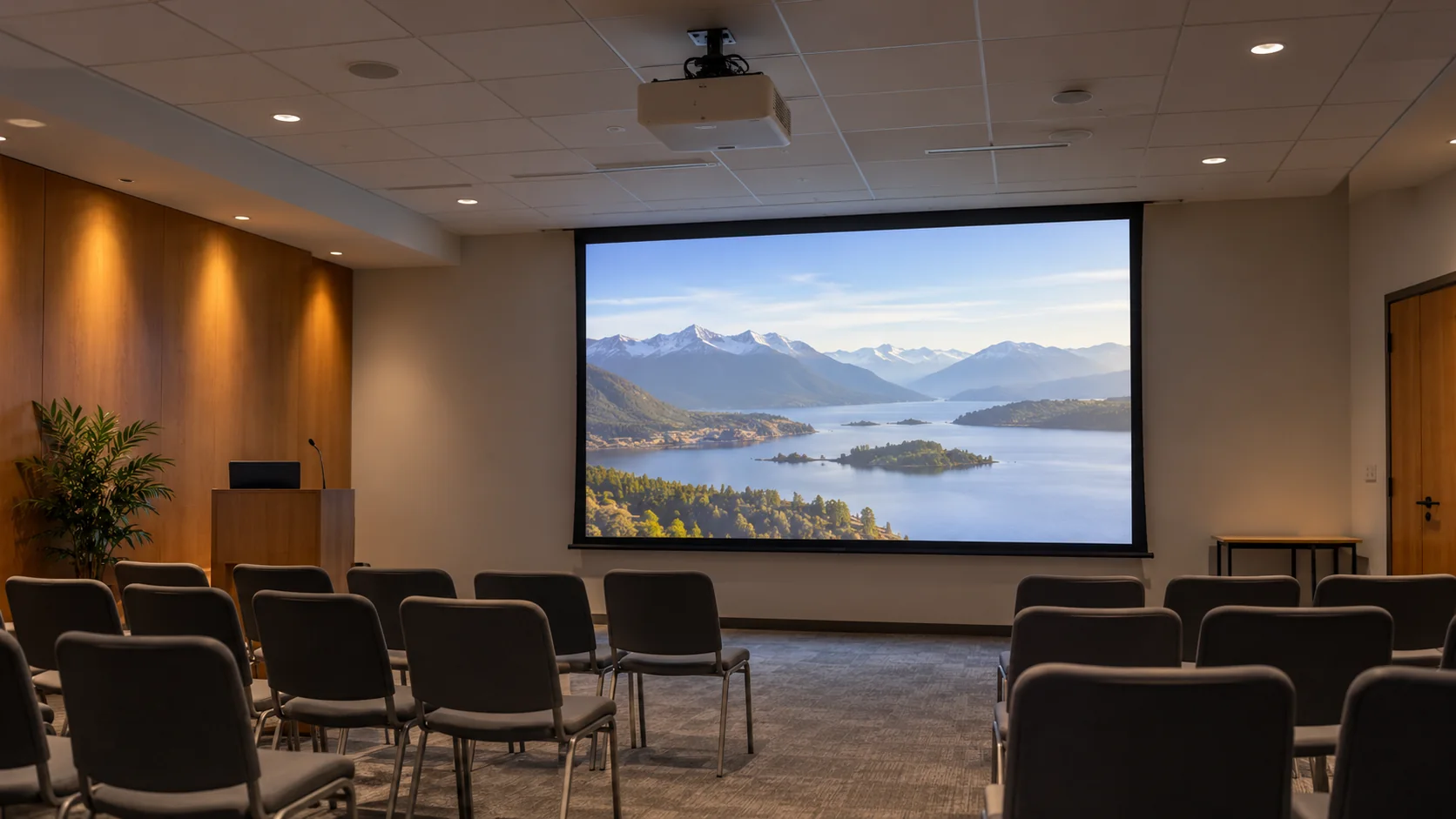
For front vs rear projection, choose front when there is no protected, usable space behind the screen. Consider rear when the projector, its beam and service access can sit behind a screen made to transmit the image, and keeping presenters out of the front beam matters.
Compare the real optical path, complete occupied depth and audience view before buying screen material. A tidy-looking screen position can still leave the projector in a doorway or the service area full of stored equipment.
Should you choose front or rear projection?
Choose front projection when the projector and its beam fit on the audience side; consider rear when a protected area behind the screen can hold them. Neither layout wins for every room. The useful comparison includes the screen surface, presenter movement and all the space the equipment will occupy.
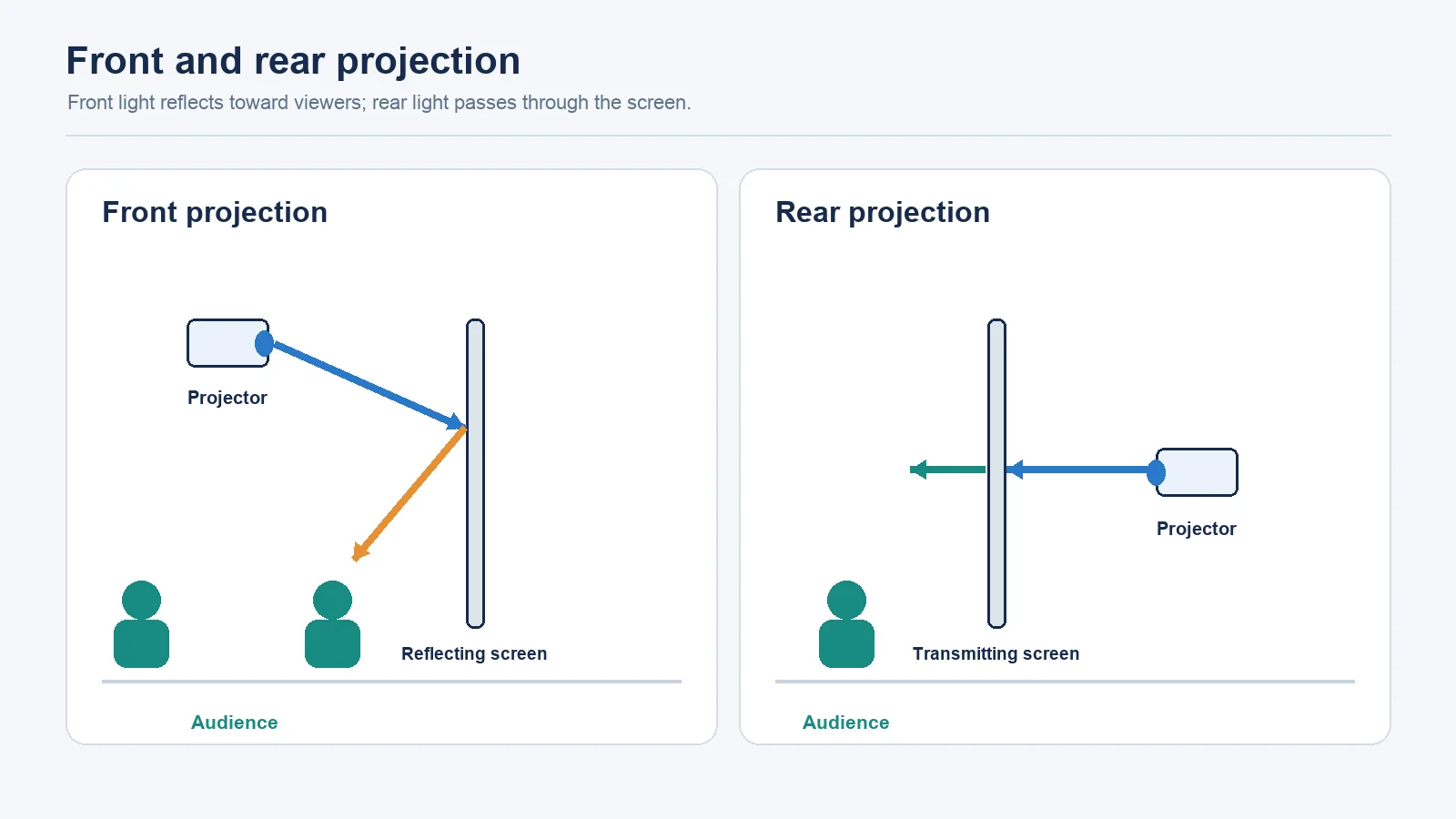
Front projection sends light toward a reflecting surface from the audience side. Rear projection sends it through a transmitting surface from the opposite side. That difference determines which parts of the room carry the equipment and which movements can interrupt the picture.
| Item | Front projection | Rear projection |
|---|---|---|
| Light path | Light reaches the screen and reflects toward viewers | Light passes through the screen toward viewers |
| Required surface | A surface specified for front reflection | A surface specified for rear transmission |
| Projector and beam | On the audience side of the screen | On the opposite side from the audience |
| Presenter in the beam | Can cast a shadow on the image | Front-stage movement stays outside the rear beam |
| Space to plan | Projector position and beam within the room | Protected rear area for throw, equipment and access |
| Further checks | Image orientation, surface identity, routes and audience view | The same checks, applied to the rear layout |
In a meeting room with a screen against a solid wall, front projection may be the feasible starting point. At a stage event with a usable backstage area, rear projection may keep a roaming presenter outside the beam. The backstage area still has to work as an equipment location.
For a retail window, start by marking where viewers stand and which side can house the projector. At home, include the seats and normal walking route on the same plan. If you are still choosing between a painted wall and a separate surface, the paint-versus-screen comparison covers that earlier material decision.
What changes when the projector moves behind the screen?
The image needs the correct reversal, and the screen needs to transmit light toward the audience. These are separate requirements. Moving the projector changes the direction from which the picture reaches viewers, so familiar letters can appear backward even when the image fills the screen and looks neatly aligned.
The Epson Home Cinema 980 projection-mode guide describes a Rear setting that flips the image horizontally for projection behind a translucent screen. Its Rear/Ceiling setting adds top-to-bottom reversal for the corresponding mounted arrangement. Those menu names belong to the named model; another projector may organize its settings differently.
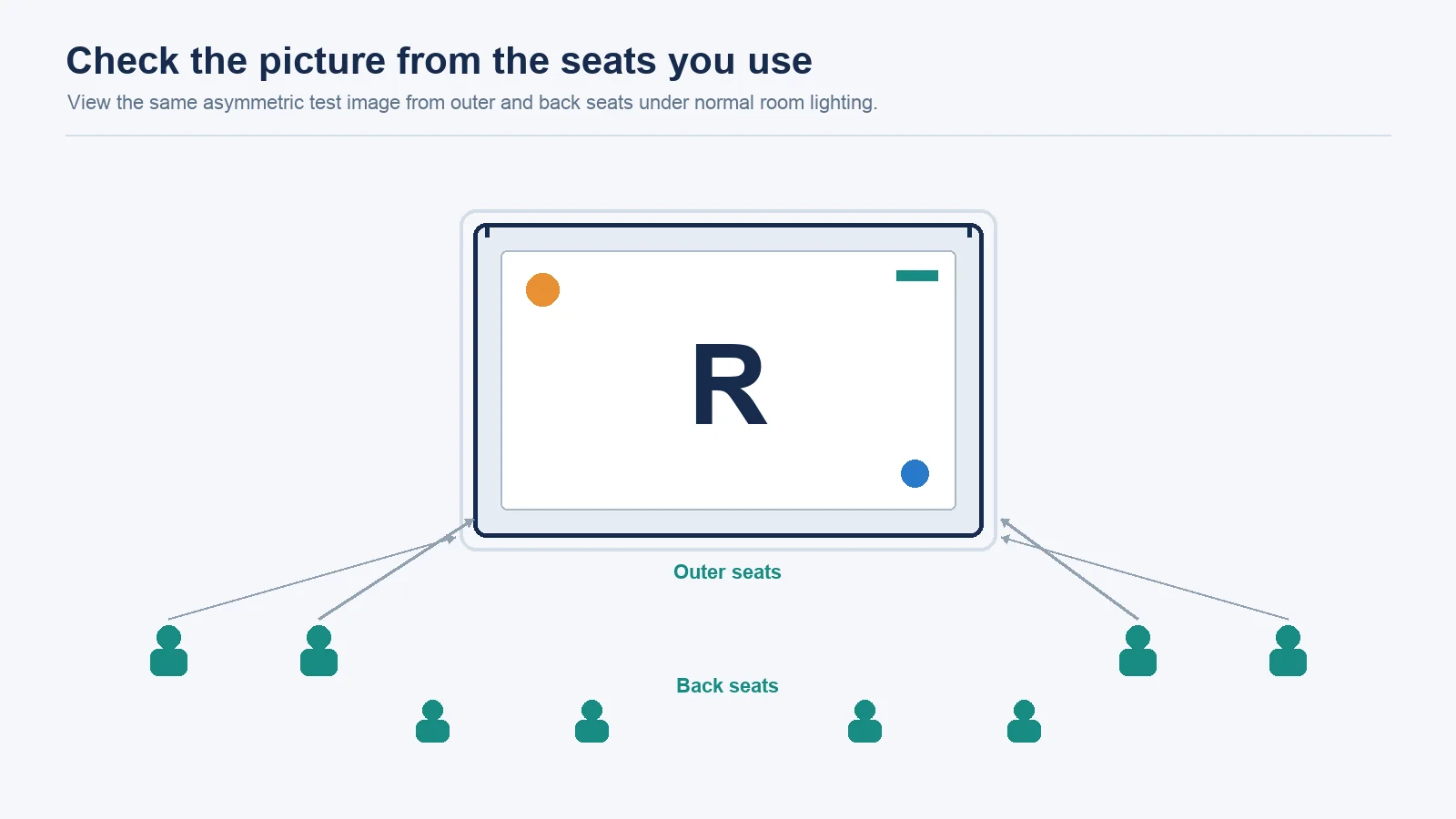
Imagine a meeting slide with a company name and a label in each corner. A photograph may look plausible when mirrored, but those labels show whether the audience is reading the intended image. Use the audience side as the reference when judging the result.
The same model’s placement guidance prefers the projector square to the screen. Start the drawing with the lens facing the intended surface, then account for the actual model’s positioning options. This keeps the proposed equipment position visible before anyone commits to a screen location.
A front reflecting surface and a rear transmitting surface have different jobs. The screen-materials guide explains the construction choices in more detail. Here, the question is whether the specified surface is made for the direction your light will travel.
How much space will the complete layout occupy?
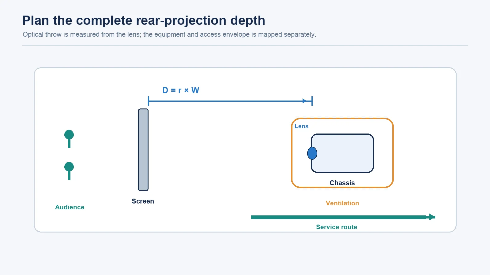
Optical throw and complete occupied depth are different measurements. Calculate throw from the active image width and the actual lens ratio, starting at the lens. Then map the chassis, the ventilation space required by that model and a usable service route. A rear-room decision needs all of those fields.
The BenQ explanation of throw ratio defines the ratio as distance divided by width. Written the other way around, the calculation is D = r × W: optical distance equals throw ratio multiplied by image width. Keep the units consistent and use the actual lens or zoom range for the proposed equipment.
Width means the active picture’s horizontal dimension. If you are starting from a diagonal size, establish the picture shape first; the aspect-ratio guide covers that choice.
| Field | What to enter | Source of the value |
|---|---|---|
| Active image width | Horizontal picture width, not diagonal | Chosen screen size and aspect ratio |
| Lens throw ratio or zoom range | The range for the exact projector and lens | Model specifications or distance chart |
| Optical throw | D = r × W, measured from lens to screen | Calculation checked against the model’s chart |
| Lens to back of chassis | The equipment extending behind the lens reference | Dimension drawing for the proposed orientation |
| Ventilation space | Required open zones around the equipment | That model’s placement instructions |
| Service and access route | Space to reach the equipment and its connections | Actual room plan and intended access |
| Required versus available depth | The complete layout compared with usable room depth | Combined plan with doors, walls and stored items marked |
As an arithmetic example, a 100-inch image with a 16:9 shape is approximately 87.2 inches, or 2.21 metres, wide. The width calculation is diagonal × horizontal proportion ÷ the square root of the sum of the squared proportions. Use that width in the throw calculation, then check the result against the chosen model’s published chart.
For a named placement example, BenQ gives the X500i a 100-inch image at 5 ft. That is optical distance from the lens, not total rear-room depth or evidence of compatibility with a rear screen.
The placement guide linked above also calls for ventilation space around and under the projector with its vents unobstructed. On your plan, show where those zones sit relative to the chassis. Service access may sit beside the equipment or behind it; overlapping zones need to be drawn, so a simple addition does not count the same area twice.
For a store room behind a stage, draw the shelving and the open door as well as the screen. If the only way to reach a connection is through the planned beam, revise the equipment or access position before calling the rear area usable. Leave unknown dimensions as project inputs until the actual equipment drawing supplies them.
Does a rear-mode setting make the whole system compatible?
No. A working rear-mode setting corrects image orientation; it does not make a front-only surface transmit the picture. Record image orientation, screen surface and light-path routes as independent results. A readable slide can pass the orientation check while the proposed material or the route behind it still needs changing.
Use this approval card with the actual equipment and surface under consideration. It is a practical way to organize the decision, based on the distinction between menu reversal and transmission in the guide above.
| Check | How to record it | Pass only when | Does not prove |
|---|---|---|---|
| Image orientation | Read a non-symmetric image with letters and corner labels from the audience side | The labels read correctly in the intended installed orientation | That the surface suits the layout |
| Screen surface identity | Record the exact product, maker-specified front/rear/dual use, audience-facing side and top edge | The maker specifies that surface for the selected layout and orientation | Image quality from every seat |
| Light path and routes | Mark the beam, presenter movement, walking routes on both sides and equipment access | No route crosses the beam during the intended use | Brightness from the audience seats |
For example, you may successfully mirror the image on a temporary surface while planning to order a different screen. Keep the surface result open until the exact ordered material is identified. Approval belongs to that material, not to the appearance of the menu.
Likewise, a route check should describe the event as it will run. An empty stage during setup may hide a crossing that appears when someone brings a lectern into position. A fixed room may look clear until the rear cupboard opens. Record each result separately so that the unresolved item leads to a specific change in the plan.
Which light paths and walking routes must stay clear?
Keep the beam corridor clear on whichever side holds the projector. Front projection puts that corridor in the audience-side room; rear projection moves it behind the screen. Presenters can move in front of a rear screen, while staff, stored items and equipment backstage still need routes outside the projected light.
For a meeting room, draw a presenter moving between the lectern and the screen. Include the moment when someone points to a chart, not only the position where they begin speaking. A front layout works better when that movement stays clear of the planned beam.
At an event, follow the route from the stage wing to the equipment area. A rear arrangement can put a speaker outside the beam while leaving a crew member’s normal shortcut directly through it. Moving that shortcut or changing the equipment position addresses the actual obstruction.
Storage behind a screen deserves the same attention. A trolley parked outside the beam during setup may move during the presentation. Mark the area that must stay clear and choose a different parking place before the room is in use. The route check covers the room as it will run, including the people who operate it.
If the picture itself looks uneven, distinguish an interrupted beam from a surface issue before changing the layout. The screen-wrinkle guide explains surface flatness.
How do you compare brightness from the seats you will use?
Compare the actual screen and projector from the outer and back seats under the room’s normal lighting. The surface and coating affect ambient-light behavior, so front or rear placement alone cannot settle the picture-quality question. Use the same intended content and lighting conditions when you assess the candidate layouts.
The AVIXA authored screen comparison notes that front-screen ambient-light resistance varies with material and coating. In a meeting room, look at small slide labels from the outer seats as well as a photograph from the centre. For a deeper explanation of angular behavior, use the gain-and-seating guide.
Where does our front-projection silicone film fit?
Puremorfilm makes film with a silicone functional surface, and our projection-screen film fits a front-projection layout. We supply it without back adhesive and as a whole piece. For a front-screen project, consider it after settling the screen position and the audience-side equipment area.
Our projection-screen film is a paint-free material with a silicone functional face, distinct from PVC, melamine, PP and PETG decorative faces. The silicone surface is inherently flame-retardant, with higher grades up to UL 94 V-0 available on request. In the manufacturer’s laboratory tests, coffee, red wine and soy sauce left at 25°C for 24 hours wiped off with no obvious change. We use a No DOP formulation. Samples are free.
Film data does not establish installed-screen optical or system performance; the surface flame statement also stays at material level. With its leather-like feel and some elasticity, the material is not for floors, stovetop counters, shower floors or walked-on areas. For ongoing care of the chosen surface, our screen-cleaning guide addresses cleaning separately.
Which layout should you approve before buying a screen?
Approve the layout before ordering its screen material. Start with front projection where a protected rear zone is unavailable; compare a rear system when the depth worksheet and the independent approval card support it. Then assess the proposed surface from the seats people will use, with the normal room lighting.
| Situation | Start with | Confirm before ordering |
|---|---|---|
| No protected rear area | A front layout | Audience-side equipment position and routes |
| Presenter moves through the image area and protected rear depth exists | Comparison with a rear system | Complete occupied depth and all approval-card results |
| Shop window or display viewed from one side | The actual audience position | Which side holds the projector and which surface faces viewers |
| Room with strong ambient light | The actual surface under those lights | A usable picture from the intended seats |
| Mixed or uncertain requirements | Both worksheets before a material order | A resolved space plan, surface identity and audience view |
Work through the purchase in this order:
- Fill the depth worksheet for the proposed screen and equipment.
- Complete the independent orientation, surface and route checks.
- View the proposed surface from outer seats under normal lighting.
- Order material specified for the approved layout.
For a window display, that sequence starts with the pavement-side viewer. For a meeting room, it starts with the screen location and the presenter’s working area. The same drawing can then show where someone reaches the equipment for service.
If the project requires rear projection, our projection-screen film is not the right material, because it is made for front projection only. For a front-layout enquiry, contact us with the screen size, intended front layout, projector or lens model, quantity and sample purpose.
Frequently Asked Questions
Can you use any projector for rear projection?
No, not by assumption. A suitable setup needs the image-orientation option, lens geometry that fits the available optical path and a surface specified to transmit the picture toward the audience. The equipment and material need to work together in the proposed layout.
Do you need a special screen for rear projection?
Yes. The screen must be specified for rear projection or transmission. A projector menu can reverse an image, but it cannot convert a front-only surface into the required transmitting material.
How much space do you need behind a rear projection screen?
There is no single figure for every setup: the space behind the screen has to hold the lens-to-screen throw plus the projector’s chassis, its ventilation zones and service access. The depth worksheet separates those fields so you can compare the complete arrangement with the area available behind your screen.
What material should I project on?
A reflecting surface suits front projection; a material specified to transmit the image suits rear projection. The selected construction, mounting and intended viewing side should match that layout.
Is rear projection better than front projection?
No, not in general. Rear projection fits when protected rear space exists and separating front-stage movement from the beam helps the presentation. Front projection can fit a room where that rear equipment area is unavailable.